19 Results
View results:
Sort by:
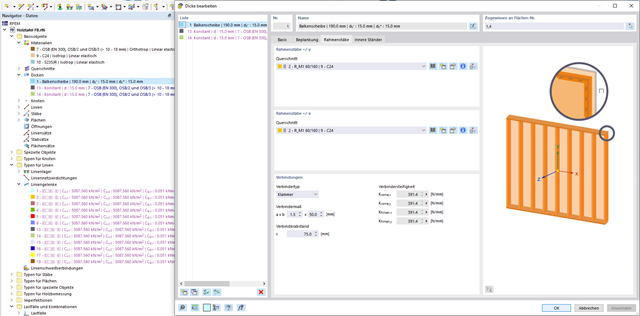
In this article, the calculation of a timber panel wall with the beam panel thickness type is compared with a manual calculation.

Plate girder is an economical choice for long spans construction. I-section steel plate girder typically has a deep web to maximize its shear capacity and flange separation, yet thin web to minimize the self-weight. Due to its large height-to-thickness (h/tw) ratio, transverse stiffeners may be required to stiffen the slender web.

Surfaces in building models can be of many different sizes and shapes. All surfaces can be considered in RFEM 6 because the program allows to define different materials and thicknesses as well as surfaces with different stiffness and geometry types. This article focuses on four of these surface types: rotated, trimmed, without thickness, and load transfer.

The reinforced concrete design for fire situations is carried out according to the simplified method based on EN 1992-1-2, Clause 4.2. The "zone method" described in Annex B.2 is used: The cross-section is subdivided into a number of parallel zones of equal thickness, and their temperature-dependent compressive strength is determined. The reduced load-bearing capacity in the event of fire exposure is thus represented by a reduced structural component's cross-section with reduced strengths.
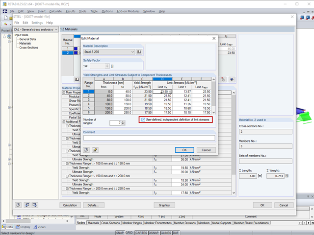
The limit stresses in RF‑/STEEL can be user-defined for each thickness range.

The additional loads from self‑weight are usually composed of several layers; for example, classic floor and ceiling layers in buildings, or road coatings for bridge constructions. When defining load definitions in RFEM and RSTAB, you can use the multi-layer load to define the individual layers with thickness and specific weight.
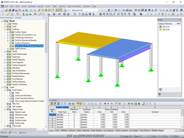
Surface thicknesses can be visualized in the model using various colors.
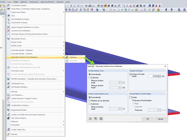
RFEM allows you to automatically generate surfaces from modeled members. This has the advantage that, for example, the surface thicknesses of a steel section are generated automatically.

In the RF-/FOUNDATION Pro add-on module, you can select the automatic dimensioning of the foundation plate geometry. In the dialog box for the design parameters of the foundation plate, you can, for example, specify the increment for the increase of the base area and the foundation plate thickness. You can also automatically increase the covering for a stabilizing effect of the geotechnical designs.

For cross‑laminated structures with large spans, downstand beams or hybrid structures are often used. They can be modeled in RFEM 5 by using surfaces and member cross‑sections. In both structural systems, curved downstand beams are also possible without any problems. In the case of the curved surface, the member is always appropriately generated by means of the automatic member eccentricity with the thickness distance of the surface and the member. The downstand beam can also be connected flexibly by means of a line release.
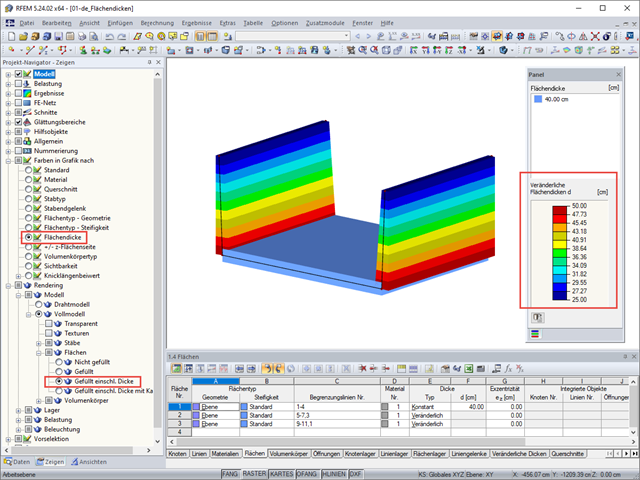
RFEM 5 allows you to show the variable surface thicknesses as a color gradient.
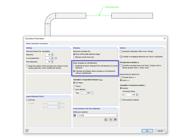
In cross‑sections created in SHAPE‑THIN, the openings, such as bolt holes, can be modeled by using the elements with zero thickness. The program provides two options for calculating shear stresses in the area of such null elements.

According to Book 631 of the DAfStb (German Committee for Structural Concrete), Chapter 2.4, the structural behavior of ceilings changes if their continuous support by walls is interrupted in areas of openings. Depending on the length of the opening area and the plate thickness, measures are necessary regarding the analysis of the ceiling in the area of the opening.
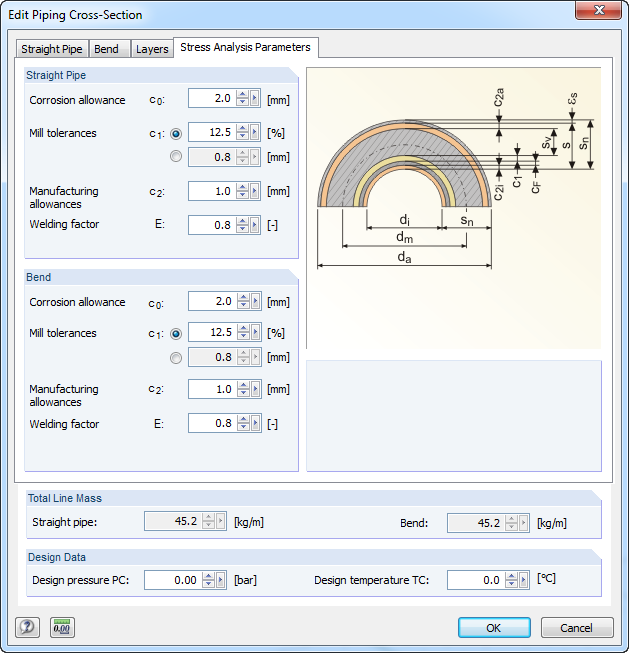
For stress calculations, some standards use the "wall thickness analysis". We get the wall thickness by subtracting corrosion, abrasion allowance, manufacturing allowances (threading, grooving, and so on), and mill tolerances from the nominal wall thickness. All necessary values can be entered in the "Piping Cross‑Section" dialog box, "Stress Analysis Parameters" tab.
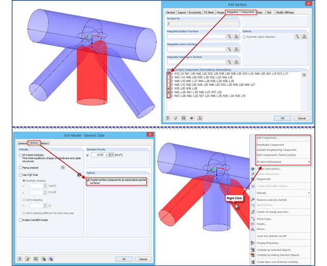
If intersections created in RFEM 4 are opened in an RFEM 5 file, the file management of intersections remains in the old format for compatibility reasons. Thus, the individual partial surfaces of the intersection can be activated or deactivated using only the "Integrated/Components" tab, all partial surfaces can only have the same thickness, and it is impossible to use the separate FE mesh refinement for the individual surface components.
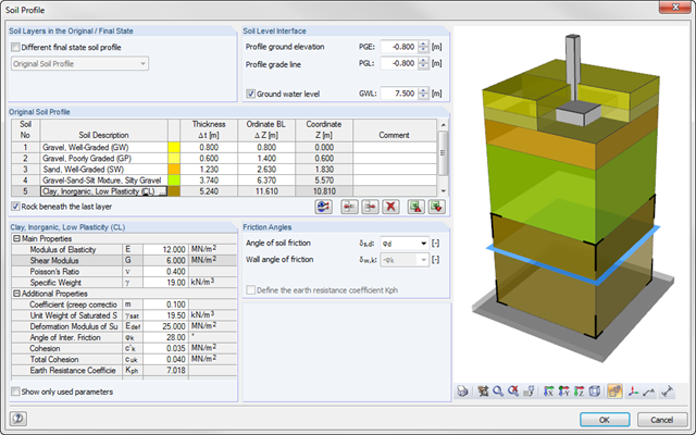
As of program version x.06.1103, you can enter a soil profile in RF‑/FOUNDATION Pro. This gives you the advantage of setting several soil layers with different soil parameters above and below the foundation base. To enter the soil layers, there is a library with various soil types that can also be extended with user‑defined soils. The user-defined soil profile is shown in an interactive information graphic. Any change (for example, a soil thickness modification) is reflected in the graphic immediately.
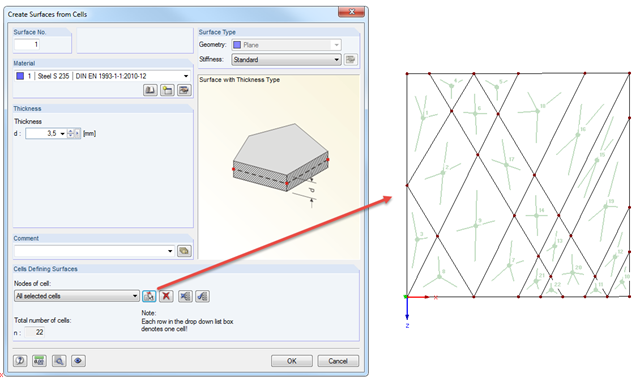
You can quickly add surfaces to grates or facade elements using the "Create Surfaces from Cells" function. This function can be found under "Tools" → "Generate Model – Surfaces" and it recognizes all the cells of the entire model. Click the "Select Cells" button to select the respective cells. In addition to the material and thickness, you can specify the stiffness of all surfaces to be created.
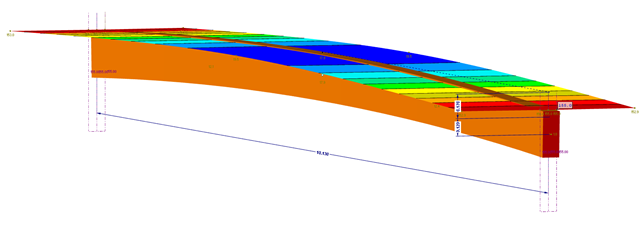
This part explains the determination of forces arising when screwing a straight cross-laminated timber plate to a curved glulam beam. For this, a glulam beam with a curved member was modeled in RFEM. The member has a precamber of 12 cm, since the preliminary design showed that the applied precamber of 6 cm will never be sufficient to maintain l/300. The dimensions of the bottom chord are 12 cm wide by 32 cm high. The plate was selected in RF‑LAMINATE as a three‑layer plate with a thickness of 8 cm.
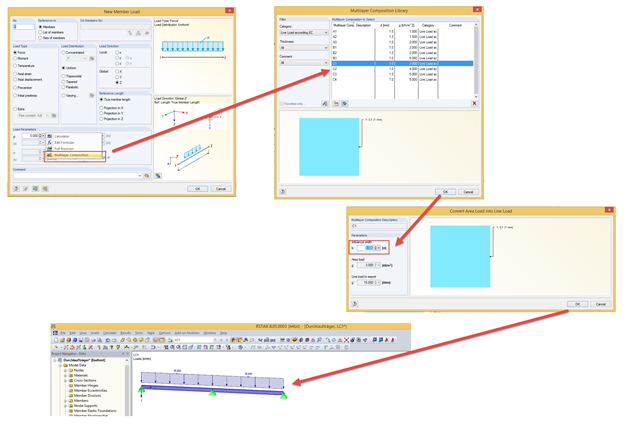
In addition to manually entering values, you can enter line loads in the "Member Load" dialog box using the "Multi-Layer Composition" function. This is a library that contains the compositions of several layers for applying loads. You can freely specify the layer structure using the parameters of description, thickness, density, or surface load, and comment for each layer.